
Understanding the core principles behind Battery Energy Storage Systems. From their architecture and operation to the key performance metrics that define their value.
1. The Role of Storage in Modern Power Systems
As grids integrate higher shares of renewable energy such as photovoltaic solar and wind, new challenges arise across the entire power system. Excess generation during central daylight hours, network curtailments, and zero or even negative electricity prices are becoming increasingly common in markets with high renewable penetration. These issues are further amplified by electrical infrastructures originally designed for systems based on synchronous generation, which traditionally provided grid stability and inertia.
Battery Energy Storage Systems (BESS) provide the flexibility that modern grids require. They absorb excess renewable generation, store it, and release it when the market demands it, helping to integrate low-cost but variable renewable energy into the power supply. Moreover, thanks to their inherently flexible charge and discharge operation and power electronics (inverters), BESS are ideally suited to deliver grid support services such as frequency regulation, reactive power control, and voltage stabilization.
BESS installations can be deployed either as standalone systems, directly connected to the grid to provide flexibility and ancillary services, or as hybrid systems combined with generation assets such as solar PV or wind. Hybrid configurations enable optimized use of shared infrastructure, reduced curtailments, and improved dispatchability of renewable energy, ultimately enhancing both technical performance and project economics.
2. BESS Main Components
A utility-scale Battery Energy Storage System (BESS) is an integrated asset that combines electrochemical technology, power electronics, low- and medium-voltage electrical equipment, and control systems. Each layer performs a specific function within the overall operation, and together they determine the efficiency, reliability, and safety of the installation.
| Component | Function |
| Battery Cells & Modules | The core energy-storing elements. Each cell converts chemical energy into electrical energy through electrochemical reactions. Cells are assembled into modules and connected in series and parallel to form battery strings or racks. |
| Battery Management System (BMS) | The protective and monitoring system at cell and module level. It continuously measures voltage, current, and temperature, balancing cells and controlling charge/discharge limits to ensure safe and efficient operation. |
| Power Conversion System (PCS) | The power electronics subsystem, primarily composed of bidirectional inverters, is responsible for converting DC power from the batteries into AC power for the grid and vice versa. It also includes transformers, filters, and protection devices that regulate and manage power flow between the BESS and the external grid. |
| Low- and Medium-Voltage Equipment | Switchgear, circuit breakers, transformers, and cabling that provide electrical connection, protection, and distribution between the BESS, the substation, and the grid. |
| Thermal Management System (TMS) | Maintains optimal operating temperature through HVAC or liquid-cooling systems, preventing overheating and reducing degradation — factors that directly impact efficiency and lifetime. This subsystem typically accounts for most of the BESS auxiliary power consumption. |
| Energy Management System (EMS) | The control system that manages dispatch strategies, operational setpoints, alarms, and communication with SCADA systems and grid operators. The term EMS can also refer to the voltage interface level at which the BESS connects to the generation assets and the grid. |
| Auxiliary Systems & Balance of Plant (BoP) | Includes safety and fire-suppression systems, auxiliary power supplies, lighting, and the physical interface to the substation and site infrastructure. |
BESS design is typically modular, allowing capacity to scale from a few megawatt-hours to several hundred. Commercial BESS solutions are generally supplied as containerized systems, integrating batteries, power conversion equipment, and auxiliary systems within standardized enclosures. This approach enables faster deployment, simplified logistics, and easier maintenance, while ensuring consistent quality and performance across projects.
3. BESS Architecture and Topology
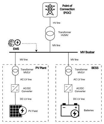
BESS can be integrated into a power plant using different coupling architectures, depending on how the storage system is electrically connected to the generation source and the grid. Two main configurations can be distinguished: AC-coupled and DC-coupled systems.
In an AC-coupled configuration, the battery system is connected on the AC side, upstream of the PV inverter, usually at medium voltage. This is the most common topology in utility-scale projects, as it allows for independent operation and metering of both the PV plant and the BESS — a feature that is typically a key requirement for front-of-the-meter applications.
AC coupling also enables the hybridization of existing plants, allowing storage to be added to operational PV or wind facilities without major redesigns. Moreover, this architecture supports the integration of multiple generation technologies — such as solar, wind, and storage — within the same electrical infrastructure. It offers greater flexibility for retrofits, simplified maintenance, increased availability, and enhanced capability to provide grid-support functions such as frequency regulation, reactive power control, and voltage stabilization.
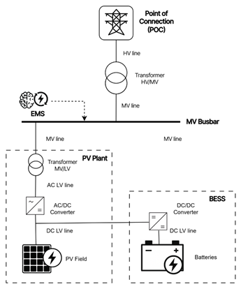
In a DC-coupled configuration, the PV arrays and the battery racks are both connected on the DC side of a shared power conversion system (inverter), enabling direct energy transfer between the PV field and the battery without intermediate AC conversion. This integrated design can reduce conversion losses when the BESS is charged directly from the PV field — although efficiency is typically lower when charging from the grid. DC coupling is therefore often used in behind-the-meter or small-scale applications, where compactness and simplified installation are key advantages.
Despite posing challenges such as complex metering requirements and a distributed, more atomized equipment layout, DC coupling has recently gained attention in certain utility-scale projects, where it enables energy recovery from PV clipping and improved utilization of surplus DC energy that would otherwise be curtailed. However, it is not yet the standard configuration recommended by most equipment manufacturers for utility scale applications, primarily due to integration complexity and regulatory constraints.
3. How Energy Flows and Where Losses Occur
Without considering the energy flow from generation to the MV busbar or from the MV busbar to the grid (point of connection), the operation of a BESS can be understood as a closed energy loop referenced to the MV busbar. During charging and discharging, power flows through a sequence of electrical and electrochemical stages, each introducing partial losses that together define the Round-Trip Efficiency (RTE) of the system.
From the MV busbar to the battery cells, the charging path includes the MV cable and switchgear, the MV/LV transformer, AC and DC cabling, the Power Conversion System (PCS), and the battery itself. Each component is characterized by an individual efficiency term (η), and the product of all these efficiencies determines the overall charging efficiency (ηcharge) which—along with the battery’s internal efficiency and the discharge path—forms the total RTE of the system.
| Step | Component | Description | Symbol | Typical Efficiency (η) |
| 1 | MV Cable & Switchgear (AC) | Resistive and contact losses along the MV feeder to the BESS bay, typically excluded from manufacturer RTE values, as the battery limit is usually defined at the MV switchgear. | ηMV | 0.995 – 0.999 |
| 2 | MV/LV Transformer (AC) | Includes both core (no-load) and copper (load) losses in the step-down transformer. | ηTR | 0.985 – 0.995 |
| 3 | AC-LV Cabling & Protection (AC) | Short low-voltage AC run between transformer and PCS; includes cable and contact losses. | ηAC-LV | 0.995 – 0.999 |
| 4 | PCS — AC → DC Conversion | Bidirectional inverter operating in rectifier mode during charging. Efficiency depends on load, power factor, and temperature. | ηPCS(AC→DC) | 0.96 – 0.985 |
| 5 | DC-LV Cabling & Protection (DC) | Losses in DC busbars, fuses, and short runs connecting the PCS to the battery racks. | ηDC-LV | 0.995 – 0.999 |
| 6 | Battery Electrochemical Efficiency | Losses associated with charge acceptance — mainly ohmic resistance, polarization, and side reactions. This factor is counted once for RTE (combined for charge + discharge). | ηBATT | 0.95 – 0.99 |
During discharge, the same sequence of components is traversed in reverse (DC → AC), with equivalent efficiencies.
Notes on Auxiliary consumptions:
- Auxiliary consumption (ηAUX) includes the Thermal Management System (HVAC/TMS), control systems, lighting, and heaters. In most utility-scale BESS installations, these loads are typically supplied from the MV side through a dedicated MV/LV auxiliary transformer, rather than from the LV bus of the PCS.
- Ideally, the manufacturer should provide auxiliary power draw for charge, discharge, and standby modes, with a breakdown by subsystem. This allows adjusting the modeled consumption according to ambient temperature, since cooling demand dominates auxiliary use in most climates.
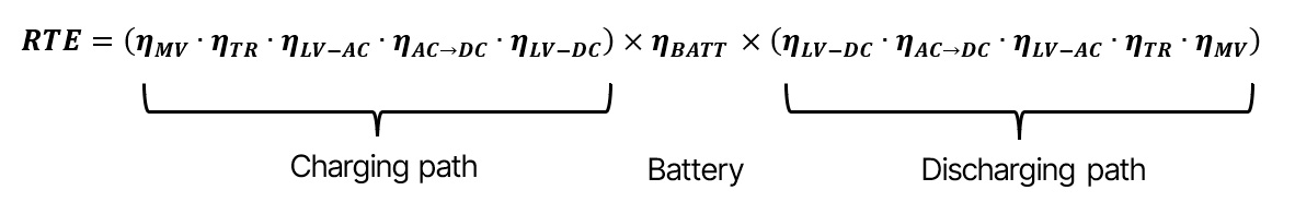
Round-Trip Efficiency Formula
The Round-Trip Efficiency (RTE), excluding auxiliary consumption, can be referenced to the MV busbar and is expressed as the product of three segments: the charging path, the battery electrochemical efficiency, and the discharging path, as shown below:
4. Battery Capacity and Degradation
Battery degradation refers to the gradual loss of energy storage capacity over time, mainly caused by electrochemical aging. At first order, degradation depends on three key operational factors:
- Number of charge/discharge cycles: The more cycles a battery performs, the greater the accumulated degradation.
- Depth of Discharge (DoD): The deeper each cycle, the higher the degradation per cycle, assuming equal operating conditions.
- C-rate: The rate at which the battery is charged or discharged. It is defined as the ratio between the battery’s nominal power (MW) and its rated energy capacity (MWh), expressed in inverse hours (h⁻¹). The C-rate determines the speed of charging and discharging: for example, a 1-hour system has a C-rate = 1, while a 4-hour system has a C-rate = 0.25. A higher C-rate increases cell stress and accelerates degradation.
In addition to cycling-related wear, temperature, SoC operating window, and storage duration also influence long-term performance. Even before entering service, a small amount of calendar degradation can occur during storage and transport between factory acceptance and commissioning.
It is important to note that the industry has not yet established a fully standardized convention for defining capacity stages. Different manufacturers may use similar terms with slightly different meanings or include certain effects within others. Therefore, when modeling a project based on manufacturer data, it is often necessary to interpret technical information carefully to avoid double-counting or overlooking certain effects.
The definitions below follow a generic and transparent framework, consistent with most technical specifications and modeling practices.
Nameplate Capacity
The theoretical or nominal DC capacity measured at the factory under standardized reference conditions — typically 25 °C, a nominal C-rate, and a full voltage window (0–100 % SoC).
This value serves as the contractual reference in the manufacturer’s datasheet and generally does not account for any prior degradation or operational limitations.
Although this is the capacity that is contracted and paid for, it does not represent the actual operational capacity, since several physical effects and operational limits must be subtracted before reaching the truly usable value.
Beginning-of-Life (BOL) Capacity
The real available capacity at commissioning, once the pre-BOL degradation (calendar losses prior to operation) has been discounted.
This reduction accounts for the effects of storage, transport, ambient conditions, and elapsed time between the factory test and site energization.
Some manufacturers include this initial degradation directly in their degradation curves (i.e., 0 cycles → SoH < 100 %), while others do not (i.e., 0 cycles → SoH = 100 %), in which case it must be accounted for separately.
It defines the starting point of the degradation model, although it may not include other operational constraints such as minimum and maximum SoC limits.
Useful Capacity
The effective DC energy available at the battery terminals, considering both capacity degradation and operational constraints such as the SoC window (e.g., 2.5–97.5 %), C-rate limits, temperature, or safety restrictions.
This represents the real usable energy that can be stored or delivered by the battery at any given time. Finally, it is important to clarify the role of battery efficiency and how it is accounted for. Electrochemical efficiency reflects the energy losses during charge and discharge, primarily due to internal voltage drop. Depending on how the model defines the useful capacity:
- If the efficiency is accounted during charging, the energy required to charge the battery equals the useful capacity plus battery losses, ensuring that the entire useful capacity can later be discharged.
- If the efficiency is accounted during discharging, the energy discharged will be the useful capacity minus the battery losses.
- A third, symmetrical approach considers the losses evenly split between charge and discharge, such that each direction corresponds to the square root of the total battery efficiency.
5. Retrofit Strategy: Replacement and Augmentation
Over time, every BESS will reach a point where its usable capacity no longer meets the project’s operational or contractual requirements. This typically occurs when the battery reaches either the manufacturer’s recommended end-of-life (EoL) defined by a State of Health (SoH) threshold (commonly 60-70%) or after a specified calendar lifetime, usually 15 or 20 ears, whichever comes first.
At that stage, operators can choose between two main retrofit strategies: battery replacement or battery augmentation. The optimal approach depends on project design, contractual obligations, and economic drivers.
Full Replacement
Full replacement involves removing the original battery racks or containers and installing new ones, restoring the system to full rated capacity.
This approach is generally adopted when:
- The degradation has reached the contractual SoH limit,
- Module compatibility with newer generations is low, or
- The control and power conversion systems are being upgraded simultaneously.
While full replacement restores performance, it also requires significant downtime, re-certification, and in some cases new compliance testing. The cost and logistics are therefore higher, but the result is a “new” battery system with a fresh degradation curve and extended project life.
Augmentation by Blocks
An alternative strategy is battery augmentation, where additional new battery blocks are progressively installed to compensate for lost capacity rather than replacing all modules at once. This modular approach provides greater flexibility and ensures smoother energy delivery throughout the project lifetime.
Augmentation is particularly advantageous in hybrid plants (e.g., PV + BESS), where the renewable generation source also degrades over time. In such cases, the optimal approach is a front-loaded capacity strategy — installing slightly more BESS capacity at the start of the project and planning progressive augmentations in later years to align storage capability with the gradually declining PV output. This method avoids excessive upfront investment and allows the system to remain properly sized at each stage of its operational life.
Whenever possible, augmentation should be anticipated during the initial system design, ensuring that the architecture supports future expansion. This includes reserving physical space for new blocks (battery containers, PCS units, and MV positions), as well as maintaining compatibility in voltage ranges, communication protocols (BMS), and control logic between existing and future equipment.
However, practical limitations may arise if the new battery blocks rely on different chemistries, form factors, or management systems, which may restrict interoperability or require partial system reconfiguration
Technical and Design Considerations for Retrofit
Both replacement and augmentation strategies must comply with the manufacturer’s design limits and warranty conditions, which typically define parameters such as maximum calendar lifetime, minimum allowable State of Health (SoH), and the environmental or operational envelope (temperature, C-rate, DoD, etc.).
In projects operating under Power Purchase Agreements (PPAs) or grid service contracts, retrofit decisions are often influenced by technical performance requirements, such as guaranteed discharge duration, available energy, or response time. In these cases, the retrofit schedule may be dictated more by contractual performance guarantees than by pure economic optimization.
Beyond technical aspects, financial and market factors play an increasingly important role in retrofit strategy. The cost of battery storage systems has followed a steady downward trend over the past decade, driven by technological innovation, economies of scale, and improvements in manufacturing efficiency. This trend suggests that future battery replacements or augmentations will likely be cheaper and more energy-dense than the original installations, which can influence the optimal timing of retrofit decisions.
However, external factors such as geopolitical tensions, supply chain disruptions, or limited access to raw materials (particularly lithium, nickel, and cobalt) can introduce volatility into long-term cost projections. Therefore, financial modeling should include sensitivity analyses that account for price fluctuations, inflation, and potential shifts in technology (e.g., transition to LFP or sodium-based chemistries).
Finally, to minimize operational risk and lifecycle cost, retrofit planning should be integrated during the early design phase.
A robust and modular system architecture allows for:
- Easy integration of new battery blocks or containers,
- Reduced downtime during interventions, and
- Simplified certification and compliance processes.
6. Glossary of Key Terms
Battery Energy Storage Systems combine concepts from power electronics, electrochemistry, and energy markets. This glossary summarizes the key technical terms used throughout this article and in manufacturer specifications.
| Term | Definition |
| Augmentation | Adding new battery modules or containers to recover lost capacity without fully replacing the system. |
| Auxiliary Consumption | Energy consumed by non-productive subsystems such as HVAC, TMS, controls, and heaters. |
| Beginning-of-Life Capacity | Capacity available at commissioning, after subtracting pre-BOL (calendar) degradation but before operational restrictions. |
| BESS (Battery Energy Storage System) | An integrated system that stores electrical energy in chemical form and releases it back to the grid or local network when required. |
| BMS (Battery Management System) | Electronic subsystem that monitors voltage, current, and temperature at cell and module level, ensuring safe and balanced operation. |
| C-rate | Charge or discharge rate relative to nominal capacity. A 1C rate corresponds to charging or discharging the full capacity in one hour. |
| Calendar Aging | Degradation occurring over time even when the battery is idle, mainly influenced by temperature and sustained high SoC. |
| Cycle Life | Total number of full cycles a battery can perform before reaching its end-of-life SoH (usually 60–70%). |
| DoD (Depth of Discharge) | Fraction of the usable energy discharged in a single cycle. A 100% DoD means the full usable capacity has been cycled. |
| EMS (Energy Management System) | The control layer responsible for dispatch strategy, operational setpoints, alarms, and grid communication. |
| End-of-Life (EoL) | The point at which the battery no longer meets the minimum performance criteria (SoH or calendar limit). |
| Equivalent Full Cycle (EFC) | A metric that normalizes partial charge/discharge events into full cycles. For example, two 50% discharges equal one EFC. |
| LTSA (Long-Term Service Agreement) | A contractual framework with the manufacturer or integrator that defines long-term maintenance, performance guarantees, and replacement conditions. |
| Nameplate Capacity | Nominal DC capacity declared by the manufacturer under standard test conditions (typically 25 °C, nominal C-rate, 0–100 % SoC window). |
| PCS (Power Conversion System) | Bidirectional inverter that converts DC from the batteries into AC for the grid and vice versa. |
| Replacement | Complete substitution of old battery blocks or containers with new ones to restore full rated capacity. |
| Round-Trip Efficiency (RTE) | Ratio of discharged energy to charged energy, including losses from power conversion and internal electrochemical processes. |
| SoC (State of Charge) | Percentage of usable energy currently stored in the battery relative to its maximum usable capacity. |
| SoH (State of Health) | Ratio between the current usable capacity and the battery’s rated (nameplate) capacity, expressed as a percentage. |
| Useful Capacity | Effective DC energy available at the battery terminals, after considering degradation and operational limits (SoC range, temperature, safety). |
7. What’s Next for Energy Storage
Battery Energy Storage System (BESS) technology continues to evolve at an extraordinary pace — from cell chemistry and cooling systems to integration architectures and digital control.
Today, lithium-ion batteries remain the dominant technology in the market, offering the best balance between energy density, efficiency, cost, and maturity of supply chains.
However, alternative chemistries such as vanadium redox flow and sodium-based batteries are gaining commercial traction, particularly in applications where longer duration, high cycling capability, or enhanced safety are prioritized over energy density.
In parallel, disruptive technologies, including solid-state, metal-air, and other next-generation chemistries, are under active research and could reshape the energy storage landscape in the coming decade.
Understanding both the core physical principles (capacity, degradation, efficiency) and the strategic lifecycle mechanisms (retrofit, augmentation, service planning) is essential to designing and operating storage systems that remain profitable, reliable, and adaptable in an evolving technological and market environment.